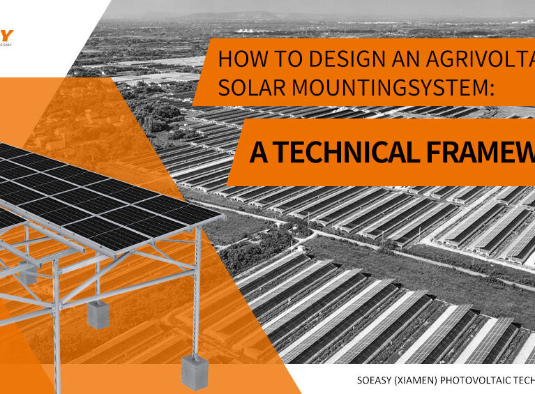
Ground-mounted solar systems are a core component of large-scale photovoltaic projects. From dozens of megawatts in utility-scale power plants to hundreds of kilowatts in commercial and industrial projects, the mounting structure, which supports photovoltaic modules, is the “skeleton” of the system. The design quality of the mounting structure directly impacts project safety, energy efficiency, and return on investment.
However, ground-mounted solar systems are exposed to various natural forces such as wind, snow, earthquakes, and soil conditions. A poorly designed mounting system can topple under extreme weather, deform under snow pressure, or sink due to unstable foundations.
Proper design ensures long-term stability of the system and avoids failures or losses caused by environmental factors.
This article focuses on three key design factors that impact the performance of ground-mounted solar systems:
- Wind Load: How to assess wind impact and design wind-resistant structures
- Load: How to handle snow, self-weight, and other static and dynamic loads
- Terrain Adaptability: How to adapt to different terrain challenges
This guide provides a systematic design approach to help you make informed, reliable decisions for your ground-mounted solar projects.
Wind Load: Assessment and Wind-Resistant Design
1. What Is Wind Load?
Wind load refers to the pressure or suction exerted on a structure by wind. For solar mounting systems, wind load is one of the most critical environmental factors affecting structural stability.
The magnitude of wind load depends on:
- Basic wind speed: The historical extreme wind speed in the project’s location (usually based on 50 or 100-year recurrence period)
- Mounting surface area: The wind-facing area of the modules and mounting system
- Wind direction: Maximum pressure is generated when wind strikes perpendicularly to the module surface
- Installation height: The higher the installation, the stronger the wind speed
- Terrain and topography: Wind profiles vary for open land, mountainous areas, and urban settings
2. How Wind Load Affects Ground-Mounted Solar Systems
| Effect Type | Manifestation | Potential Consequences |
|---|---|---|
| Overturning risk | Wind generates overturning torque, causing system to topple | Complete system failure |
| Sliding risk | Horizontal wind forces the mounting system to slide on the ground | Module displacement, cable strain |
| Structural deformation | Wind forces cause bending of posts or twisting of beams | Module micro-cracks, tracking system jams |
| Connection failure | Bolt connections loosen or break under fluctuating wind loads | Partial module detachment, chain reaction damage |
| Resonance fatigue | Wind-induced vibration causes structural fatigue | Long-term cumulative damage |
Key Areas to Watch:
- Coastal areas (frequent typhoons and hurricanes)
- Mountain wind corridors (wind speed amplification due to the venturi effect)
- Open plains (high wind speeds due to lack of obstructions)
3. Key Design Considerations for Wind Load
• Wind Load Calculation
Standards:
- China: GB 50009 “Code for Design of Building Structures”
- International: Eurocode 1 (EN 1991-1-4), ASCE 7 (USA)
Calculation Steps:
- Determine basic wind speed (or basic wind pressure) for the project location
- Adjust for terrain, height, and roughness to determine wind pressure height variation coefficient
- Calculate the wind load standard value acting on modules and mounting system
- Use limit state design methods for load combination
• Optimizing Mounting Angle and Shape
| Design Strategy | Effect | 適用シーン |
|---|---|---|
| Reduce tilt angle | Reduces wind-facing area, lowering wind load | High wind areas, low tilt design |
| Optimize layout | Higher wind load at the edges, denser support recommended | All projects |
| Airflow design | Add deflectors between rails to reduce wind pressure concentration | Large arrays |
• Additional Support Structure
| Measure | Description | 適用シーン |
|---|---|---|
| Dense posts | Reduce post spacing to improve overall stiffness | High wind areas, large spans |
| Add diagonal bracing | Form a triangular stable structure between posts and beams | All projects |
| Increase foundation depth | Improve overturning moment resistance | High wind areas |
| Pile foundation reinforcement | Use larger diameter or deeper piles | Soft soil + high wind areas |
| Weight design | Add concrete weight to the foundation | Non-penetrating foundations |
Expert Advice:
- Normal wind areas (basic wind pressure ≤ 0.35 kN/m²): Standard design suffices
- High wind areas (0.35–0.5 kN/m²): Increase post density, add bracing
- Typhoon areas (>0.5 kN/m²): Specialized wind-resistant design, consider wind tunnel testing if necessary
Load: Understanding the Impact of Snow Load and Self-Weight
1. What Are the Loads in a Solar System?
Loads refer to the forces acting on the solar mounting system, which can be categorized as:
| Load Type | Definition | Source |
|---|---|---|
| Static Load (Dead Load) | Long-term constant loads | Module self-weight, mounting structure weight |
| Dynamic Load (Live Load) | Loads that vary over time | Wind load, snow load, earthquake load |
| Construction Load | Temporary loads during installation and maintenance | Workers, tools, equipment |
2. How Loads Affect Ground-Mounted Solar Systems
| Load Type | Impact |
|---|---|
| Module self-weight | Determines post and beam cross-section size |
| 雪荷重 | Increases vertical load, affecting mounting strength and foundation compressive ability |
| 風荷重 | Generates horizontal forces and overturning moments, affecting foundation pull-out |
• Snow Load Specifics
Snow load is a critical factor in cold region solar systems:
| Issue | Description |
|---|---|
| Snow accumulation | Snow may accumulate if module tilt angle is small, increasing load |
| Uneven distribution | Wind may cause snow accumulation at array edges or in localized areas |
| Melt and refreeze | Melted snowwater refreezes under low temperatures, increasing load |
| Sliding impact | Snow sliding off may damage modules or nearby equipment |
• Soil Bearing Capacity Impact
| 土壌の種類 | Bearing Capacity | Foundation Design Impact |
|---|---|---|
| Rock | Extremely high | Shallow foundations, reliable anchoring |
| Dense sand/gravel | High | Standard pile foundations |
| Clay (hard plastic) | Moderate | Must control settlement |
| Soft clay/silt | Low | Larger foundation size or soil replacement |
| Fill soil | Low to uneven | Requires special investigation |
3. Key Design Considerations for Load
• Load Calculation
Snow Load Calculation (according to GB 50009 / Eurocode 1):
- Determine basic snow pressure (50-year recurrence period)
- Account for roof slope effect (module tilt angle’s impact on snow accumulation coefficient)
- Account for wind impact on snow distribution (uneven distribution factor)
- Calculate standard snow load value
Load Combination:
- Basic combination: 1.2 × dead load + 1.4 × larger of snow or wind load
- Extreme combination: Consider simultaneous wind and snow load conditions
• Foundation Design
| Load Condition | Recommended Foundation Type | Explanation |
|---|---|---|
| Low load, good foundation | Screw piles | Fast installation, low cost |
| Medium load | Precast concrete piles | Standardized, good quality control |
| High load, soft soil foundation | Bored cast-in-place piles | High load capacity, low settlement |
| High load, rock foundation | Anchor rod foundation | Leverages rock capacity |
• Module Layout and Tilt Angle Optimization
| Strategy | Effect | Applicable Scenario |
|---|---|---|
| Increase tilt angle | Promotes snow shedding | Heavy snow areas (recommended tilt ≥25°) |
| Optimize array spacing | Avoid snow falling from front rows to back rows | Heavy snow areas |
| Add snow barriers | Control snow shedding path | Below important facilities |
Terrain: Adapting to Natural Features of the Land
1. How Does Terrain Affect Ground-Mounted Solar Systems?
Different terrains impact the design of mounting systems directly. Elevation changes, soil conditions, and drainage characteristics affect stability, foundation design, and installation cost.
| Terrain Type | Main Challenge | Design Impact |
|---|---|---|
| Flat land | Uniform wind load, drainage | Simple foundation design |
| Sloped land | Stability, soil erosion | Adjustable mounting, terraced layout |
| Mountainous/hilly | Irregular terrain, difficult construction | Custom design, modular layout |
| Soft soil/marsh | Low bearing capacity, settlement | Special foundation |
| Rocky ground | Difficult foundation work | Anchor rod foundation |
2. Terrain Types and Design Implications
• Flat Land
Characteristics:
- Regular terrain, small elevation change
- Easy foundation design and construction
- Suitable for standardized and large-scale systems
Design Key Points:
- Focus on wind and snow load uniformity
- Use standard layout plans
- Simple drainage design
適用される Solution: Standard fixed mounts, single-axis tracking system
• Sloped Land
Characteristics:
- Ground with tilt angle
- Need to consider stability along slope direction
- Soil erosion risks
Design Key Points:
- Use adjustable mounts to accommodate slope
- Align along contour lines to minimize soil movement
- Add anti-slip measures (e.g., anti-slip teeth, blocks)
- Add drainage channels to prevent erosion
Technical Parameters:
- Slope <15°: Adjustable mounts usually sufficient
- Slope 15–30°: Custom design, terraced layout
- Slope >30°: Significant increase in construction cost, requires special assessment
• Irregular Terrain (Hills, Rolling Land)
Characteristics:
- Significant elevation variation
- Dispersed plots, difficult to arrange continuously
- Construction challenges
Design Key Points:
- Detailed terrain survey and 3D modeling
- Use modular design for scattered plots
- Base design must account for geological variations
- Optimize cable routing to suit terrain
Common Design Mistakes to Avoid
1. Underestimating Wind Load in High Wind Areas
Symptoms:
Using the same wind-resistant design parameters for all projects without adjusting for local wind speeds.
Consequences:
Mounting system failure or structural damage in high wind areas.
Correct Approach:
Calculate based on basic wind pressure for the project location’s 50-year recurrence period and add support in high wind areas.
2. Ignoring Soil Bearing Capacity
Symptoms:
Proceeding without soil survey and using standard foundation designs.
Consequences:
Foundation settlement, tilting of mounting system, uneven module stress.
Correct Approach:
Conduct a site-specific geotechnical investigation, and design foundations based on soil bearing capacity.
Comprehensive Design for Optimal Performance
The reliability of a ground-mounted solar system begins with a comprehensive consideration of key design factors.
Three Core Design Factors Recap
| Factor | Core Consideration | Design Strategy |
|---|---|---|
| 風荷重 | Wind speed, direction, terrain effect | Increase post density, add bracing, deepen foundations |
| Snow Load/Self Weight | Snow pressure, soil bearing capacity | Increase tilt angle, optimize foundation design, load combinations |
| Terrain Adaptation | Slope, elevation change, soil conditions | Adjustable mounts, custom foundation, terraced layout |
SOEASY Ground Mounting Solutions
As a professional solar mounting system provider, SOEASY offers complete solutions that cover various terrain and load conditions:
- Standard Product Line: Fixed tilt mounts, adjustable tilt mounts, single-axis tracking systems
- Terrain Adaptability: Suitable for flat, sloped, mountainous, soft soil, and rocky terrains
- Wind/Snow Design: Custom designs based on wind and snow pressure
- Foundation Options: Screw piles, precast piles, bored cast-in-place piles, anchor rod foundations, weighted foundations
- Full Lifecycle Service: From terrain survey, load calculations, structural design, to installation guidance
FAQ
What is the key factor to consider in wind load design for ground-mounted solar systems?
The location’s basic wind speed 及 terrain type are critical factors for wind load calculation.
How does snow load affect ground-mounted solar systems?
Snow load can increase vertical pressure, affecting the system’s strength and foundation capacity.
What terrain considerations impact ground-mounted system design?
Slope, soil type, and drainage characteristics must all be considered when designing foundations and mounting systems.
English
