English


 Post by
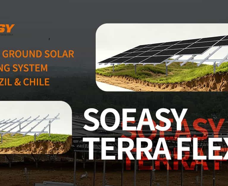
Terrain-following ground-mount solar systems eliminate expensive cut-and-fill land grading by utilizing articulated post-to-beam joints, telescopic leg adjustments, and dual-axis slope tolerances (North-South and East-West) to conform directly to undulating hills and steep gradients.
As flat, low-cost parcels near substations disappear globally, utility-scale and commercial solar developers are increasingly building on marginal, rolling, and mountainous land—from the Andean foothills in Chile and hilly states in Brazil to rugged terrain across Southern Europe and Japan.
For structural engineers and EPC contractors, deploying standard fixed-tilt racking on irregular terrain triggers severe bottlenecks: massive civil earthworks, uneven row shading, and mechanical stress on solar modules. This technical guide examines the structural mechanics, foundation engineering, and layout strategies required to build bankable PV power plants on complex topography.
1. The Three Engineering Challenges of Sloping & Undulating Sites
When ground elevation changes across both North-South (N-S) 及 East-West (E-W) axes, standard rigid racking systems experience critical failure modes:
- Cumulative Purlin Torsion & Module Micro-Cracking: Rigid longitudinal purlins cannot bend smoothly over undulating East-West ridges. Forcing frames to conform to uneven post heights induces torsional twisting in the torque tube or purlin, transferring mechanical stress directly onto large-format (600W–720W+) glass-on-glass bifacial modules.
- Inter-Row Shading on North-Facing / South-Facing Slopes: On sloping terrain, shadow lengths change dramatically depending on whether the hillside faces toward or away from the equator. Uniform row spacing calculated for flat land causes severe winter shading losses on reverse slopes.
- Soil Erosion & Civil Permitting Bottlenecks: Bulldozing native topsoil to create flat benches destroys natural root systems, accelerating monsoon or seasonal runoff erosion around pile foundations and triggering strict environmental compliance delays.
2. Mechanical Architecture of a True Terrain-Following Mounting System
To build reliably on irregular topography without civil grading, a specialized sloping ground-mount structure—such as the SOEASY Terra FLEX Sloping Ground Mounting System—incorporates four core mechanical innovations:
A. Dual-Axis Slope Compensation (N-S & E-W Articulation)
- North-South Slope Adjustment: Telescopic rear legs and multi-angle pivot brackets allow installers to maintain the exact optimal module tilt angle regardless of whether the ground rises or drops along the N-S axis.
- East-West Terrain Following: Articulated purlin connectors and slotted beam joints absorb E-W ground undulations smoothly, allowing adjacent tables to follow natural hill contours without bending structural members.
B. Height-Tolerant Post-to-Beam Interfaces
During pile driving on rocky or sloping sites, hitting bedrock can cause post embedment depths—and above-ground reveal heights—to vary by several centimeters. Engineered vertical adjustment slots at the post head absorb ±50mm to ±150mm of elevation variance on-site without requiring flame-cutting or field welding.
C. Enhanced Aerodynamic & Slope Wind-Load Engineering
Wind velocity accelerates as air flows up a hillside (topographic speedup effect under Eurocode 1 and ASCE 7). Sloping racking designs reinforce edge rows and front-leg uplift connections to handle localized wind pressure amplification on ridge crests.
D. High Strength-to-Weight Material Optimization
Combining high-tensile structural aluminum alloys (e.g., AL6005-T5) with SUS304 stainless steel fasteners—or high-strength Zn-Al-Mg coated steel for heavy-load zones—reduces dead weight for easier material transport up steep grades while maintaining 25+ year corrosion durability.
3. Foundation Engineering Matrix for Hilly & Rocky Geology
Hillside solar sites rarely feature uniform soil. Matching the foundation anchor to subsurface geology is essential to prevent differential settlement or pull-out failure:
| Subsurface Soil Condition | 推奨される太陽光発電用基礎の種類 | Key Engineering Advantage on Slopes |
| Compact Clay / Loam Hillsides | Driven C-Pile or H-Beam | Fast installation via track-mounted hydraulic pile drivers; minimal soil disturbance. |
| Weathered Rock / Gravelly Slopes | Helical Ground Screws | Threads smoothly through cobbles and fractured rock without concrete curing delays. |
| Hard Bedrock / Steep Karst | Micro-Piles (Pre-Drilled & Grouted) | Anchors directly into solid rock strata with high uplift and lateral shear resistance. |
| Sensitive Topsoil / Protected Land | Ballasted Concrete Blocks | Zero ground penetration; preserves shallow root zones and underground utilities. |
4. Layout Optimization: 1P vs. 2P Configurations on Uneven Terrain
Choosing between 1P (One-in-Portrait) 及 2P (Two-in-Portrait) table configurations significantly impacts structural performance on steep slopes:
- 1P (Single-Row Portrait) Advantage on Severe Slopes: With a lower center of gravity, narrower chord width, and shorter cantilever overhang, 1P configurations experience lower wind overturning moments on steep hillsides and offer finer granularity when stepping across abrupt terrain breaks.
- 2P (Two-Row Portrait) Advantage on Rolling Plains: On gentler rolling slopes, 2P configurations reduce the total number of foundation piles per megawatt by up to 35%–45%, lowering pile-driving labor and steel tonnage while maximizing ground clearance.
5. Field-Validated Performance in Complex Terrain Worldwide
Proven engineering on real-world hills is the ultimate benchmark for bankability. Across more than 10GW of global solar deployments, SOEASY’s terrain-adaptive mounting systems have been validated across diverse topographical extremes:
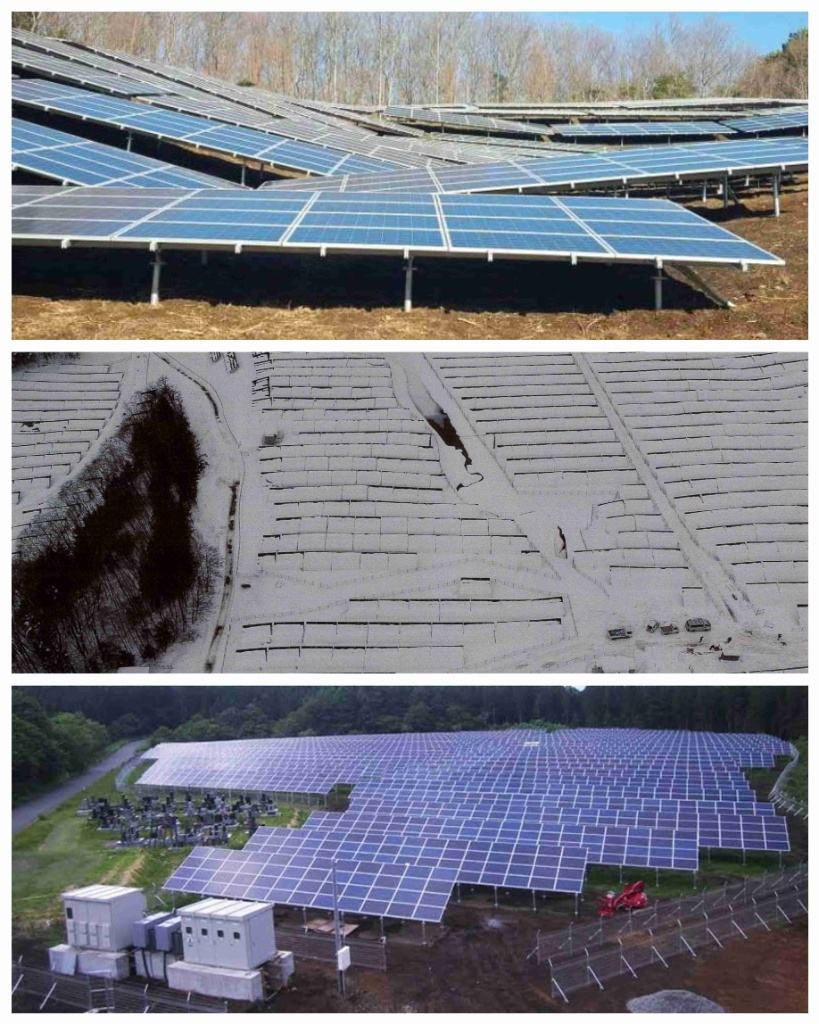
- Steep Forest-Edge Hillsides (Shizuoka, Japan & Serbia): On undulating mountainous sites with strict land-preservation rules, EPCs deployed SOEASY Terra FLEX structures to follow steep natural gradients directly—eliminating bulldozing and preventing seasonal rainwater runoff erosion.
- Rocky Mountainous Terrain (Western Bosnia and Herzegovina – 1.25MW): Engineered to withstand rugged rocky outcrops, elevation shifts, and heavy alpine wind/snow loads through custom post-height tolerances and reinforced structural joints.
(View detailed engineering case studies on our Ground PV Projects Portfolio).
Frequently Asked Questions (FAQ) — Uneven & Sloping Ground Solar Mounting
Q1: How does terrain-following racking reduce Balance of System (BOS) costs?
By adapting to natural ground contours instead of leveling the site, terrain-following racking eliminates cut-and-fill earthmoving contracts, drainage re-engineering, and re-seeding costs—typically reducing total civil and installation BOS expenses by 15% to 25% on hilly sites.
Q2: Can adjustable ground mounts maintain uniform module tilt on varying slopes?
Yes. Through adjustable telescopic legs and articulated head brackets, installers can set a consistent module tilt angle (e.g., 15°–30°) across undulating terrain, ensuring uniform string voltage and minimizing mismatch losses.
Q3: What site data is required to engineer a sloping ground-mount layout?
To optimize pile lengths, post spacing, and row pitch on uneven terrain, structural engineers require a 3D topographical contour map (DWG/DXF or KMZ with elevation data), a preliminary geotechnical pull-out test report, local wind/snow design codes, and the solar module datasheet.
Engineer Your Hillside Solar Project with Precision
Planning a ground-mount solar installation on rolling hills, rocky slopes, or irregular land? Share your site topography file (CAD/KMZ) and module specifications with SOEASY’s engineering team for a customized 3D terrain-adapted layout, structural load calculation, and factory-direct quotation.
👉 Request a Free Sloping Terrain Engineering Design & Quote
電子メール: