English


1. Why a Tile Roof Cannot Use a “Universal” Solar Mounting Solution
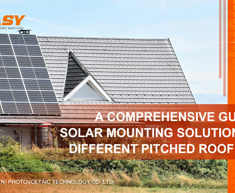
With the rapid expansion of distributed photovoltaic systems, more property owners are installing solar panels on existing rooftops. Among various roof types, tile roofs remain common in residential houses, villas, and low-rise public buildings due to their thermal insulation performance and architectural appearance.
However, although tile roofs may look similar from the outside, the supporting structure beneath them can be fundamentally different. In practice, the base structure is typically either a wooden roof frame or a reinforced concrete slab. These two structural systems differ significantly in mechanical behavior, installation methods, and long-term reliability.
If this structural difference is ignored and a single mounting solution is applied indiscriminately, serious risks may follow. For instance, incorrect anchoring may reduce wind uplift resistance. In addition, improper drilling may damage the waterproof layer and cause long-term leakage. More critically, if loads are not transferred correctly to the structural base, localized roof damage or even structural failure may occur.
Therefore, accurately identifying the structural type beneath a tile roof is the first and most important step in designing a safe and reliable solar mounting system.
2. Basic Structural Composition of a Tile Roof
Before comparing installation solutions, it is essential to understand how a typical tile roof is constructed.
A standard tile roof consists of two main layers:
2.1 Surface Layer: Ceramic or Clay Tiles
The visible tile layer provides weather protection, drainage, and UV resistance. Although tiles appear strong, they are brittle materials and are not designed to carry structural loads. Instead, they rely on overlapping placement and gravity for stability.
For this reason, tiles must never be treated as load-bearing elements. Any attempt to clamp onto tiles or bond mounting components directly to them is structurally unsafe and unacceptable.
2.2 Structural Base Layer (Load-Bearing Layer)
Beneath the tiles lies the true structural framework of the roof. This base layer carries wind loads, snow loads, maintenance loads, and the full weight of the photovoltaic system.
Solar mounting systems must penetrate the tile layer and anchor securely into this structural base. Depending on construction practices and building age, the base structure generally falls into two categories:
Wooden Structure
Common in older residential buildings and some villas, wooden roofs consist of main beams and wooden purlins (tile battens). The purlins directly support the tiles and are spaced at fixed intervals.
Concrete Structure
Modern residential and public buildings typically use reinforced concrete slabs as the structural base. Above the slab, leveling layers and waterproof membranes are installed before tiles are laid. Concrete structures provide high rigidity and overall integrity.
Once this layered configuration is understood, the installation logic becomes clear: the mounting system must transfer loads precisely to the structural base layer, not to the tiles.
3. Installation Characteristics of Wooden Structure Tile Roofs
When installing solar mounting systems on wooden structures, engineers must respect the mechanical properties of timber.
3.1 Fixing Method
First, installers carefully remove selected tiles to expose the underlying wooden purlins or beams. Accurate positioning is critical because these members are the only valid load-bearing attachment points.
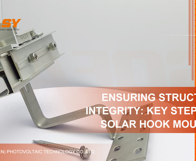
Next, stainless steel roof hooks specifically designed for wooden structures are fixed directly to the purlins using wood screws or self-tapping screws. The hook extends through the tile gap and supports the mounting rail above.
Importantly, screws must be positioned at the center of the wooden member. Drilling near the edge may cause splitting, which significantly reduces holding capacity.
3.2 Load-Bearing Characteristics
Wood is an anisotropic, elastic-plastic material. Under long-term static loads from modules and mounting systems, creep deformation may occur. Therefore, structural calculations must consider long-term strength reduction factors.
In addition, wooden roof frames typically have lower stiffness than concrete slabs. Under strong wind conditions, vibration and dynamic fatigue loads may develop. Consequently, the mounting system must provide sufficient adaptability and connection strength to resist these dynamic effects.
Beyond evaluating individual hook capacity, engineers must also assess the overall stability of the wooden roof system. Connections between beams and purlins must remain reliable after additional solar loads are introduced.
3.3 Waterproofing Considerations
After hook installation, tiles must be restored carefully. Localized cutting ensures the hook passes through without disturbing the original drainage path.
Moreover, penetration points—such as screw locations and tile-hook interfaces—must be sealed using high-quality weather-resistant materials, including butyl tape or specialized sealants. Multi-layer sealing is recommended to prevent capillary water intrusion.
Finally, installers should verify that drainage paths remain unobstructed and that no water accumulation occurs behind the hook.
3.4 Advantages and Risks
Wooden structure systems offer relatively fast installation because heavy drilling equipment is not required. For experienced teams, installation efficiency is high and tile damage can be controlled.
However, risks primarily relate to aging structures. In older buildings, wooden purlins may suffer from decay, insect damage, cracking, or reduced strength. If structural integrity is not evaluated beforehand, installation may compromise an already weakened roof system.
For older wooden structures, professional structural assessment is strongly recommended before installation.
4. Installation Characteristics of Concrete Structure Tile Roofs
Concrete roof structures dominate modern construction and provide higher rigidity and stability.
4.1 Fixing Method
As with wooden roofs, selected tiles are lifted to expose the structural base. After surface cleaning, installers drill into the concrete slab and install chemical anchors or high-quality mechanical anchors.
Chemical anchors are generally preferred because they provide strong pull-out resistance without generating expansion stress within the concrete. Metal bases—such as L-feet or adjustable supports—are then fixed to support mounting rails.
Adjustable bases are particularly useful when leveling layers or insulation layers are present, as they allow height correction to maintain rail alignment.
4.2 Load-Bearing Characteristics
Concrete slabs exhibit high stiffness and minimal deformation under load. As a result, the solar mounting system effectively rests on a rigid platform.
Furthermore, properly installed anchors provide significantly higher pull-out resistance compared to wood screws. This characteristic offers a clear advantage in resisting wind uplift forces.
Because concrete distributes concentrated loads across the slab surface, localized structural stress is minimized.
4.3 Waterproofing Considerations
Drilling into a concrete roof inevitably penetrates the existing waterproof layer. Therefore, immediate and precise sealing is critical.
Before anchor installation, drilled holes must be dry and free of dust. After installation, the interface between anchor and concrete must be fully sealed using high-performance waterproof sealant to form a protective cap.
Additionally, drilling locations should be positioned away from slab edges to prevent cracking and potential water infiltration.
4.4 Advantages and Risks
Concrete structures provide excellent stability, strong wind uplift resistance, and long-term durability. Unlike wood, concrete does not suffer from biological degradation.
However, installation complexity is higher. Drilling depth, hole cleaning, adhesive curing time, and sealing quality must strictly follow technical standards. Improper procedures may compromise both structural performance and waterproofing reliability.
5. Structural Design and Calculation Differences
From an engineering standpoint, wooden and concrete systems follow different structural logic.
5.1 Load Transfer Path
For wooden structures, loads transfer sequentially from module to rail to hook to purlin, then to beam and wall. This point-to-point load path requires precise alignment with structural members.
In contrast, concrete structures transfer loads from module to rail to base to anchor and then across the slab. This point-to-surface distribution improves redundancy and load diffusion.
5.2 Fixing Point Spacing
In wooden systems, hook spacing is constrained by purlin intervals. Designers must adapt rail spans accordingly and may need to increase rail section size when purlin spacing is large.
Conversely, concrete slabs allow more flexible anchor placement. Designers can optimize anchor spacing based on wind load calculations and rail structural performance.
5.3 Wind Uplift and Pull-Out Design
For wooden roofs, pull-out capacity depends on screw resistance and the timber’s holding strength. Connections must accommodate potential wood deformation over time.
For concrete roofs, anchor selection and embedment depth are the primary design factors. Engineers must calculate maximum uplift forces and select anchors with adequate safety margins.
6. Construction Difficulty and Efficiency Comparison
Wooden structures require precise positioning to locate purlins. Although fixing each point is relatively fast, incorrect positioning eliminates load-bearing capacity.
Concrete structures allow more flexible positioning but require impact drilling, hole cleaning, adhesive injection, and curing. Therefore, installation per fixing point takes longer and demands stricter process control.
While initial costs may be higher for concrete systems, their long-term reliability often reduces maintenance risks.
7. How to Identify the Roof Structure Type
To select the correct solar mounting solution, several steps should be followed:
- Review architectural drawings to confirm structural type.
- Conduct on-site inspection using tapping methods to distinguish between hollow and solid sounds.
- Examine exposed beams at eaves or gables.
- Assess roof condition for decay, cracks, or waterproof deterioration.
- Perform professional load calculations based on wind and snow conditions.
Only after proper evaluation should the final mounting solution be determined.
8. Common Mistakes in Tile Roof Solar Installation
Several frequent errors must be avoided:
- Treating tiles as load-bearing elements
- Ignoring structural type differences
- Using wood screws in concrete or expansion bolts in timber
- Overlooking waterproof sealing details
- Installing on aged wooden structures without assessment
Each of these mistakes can compromise structural safety and long-term reliability.
9. Conclusion: Structural Type Determines Installation Logic
Installing solar panels on tile roofs is not merely a surface operation. Instead, it is a structural engineering process that requires careful evaluation and precise load transfer design.
There is no universally “best” solution. Rather, the correct approach depends entirely on the underlying roof structure.
Through professional inspection, accurate structural identification, scientific calculation, and standardized installation procedures, a tile roof solar mounting system can operate safely and efficiently for 25 years or more.
Choose SOEASY Solar: Professional Tile Roof Solar Mounting Solutions
Understanding the structural differences between wooden and concrete tile roofs is essential. Selecting the correct mounting solution ensures system safety and durability.
SOEASY Solar provides:
- Professional structural evaluation support
- Dedicated roof hook systems for wooden structures
- Chemical anchor systems for concrete structures
- Project-based structural calculation reports
- Standardized and customized mounting components
- Full technical support from design to installation
If you are planning a tile roof solar project, click here to contact SOEASY Solar for professional technical guidance and tailored mounting system solutions.