English

 Post by
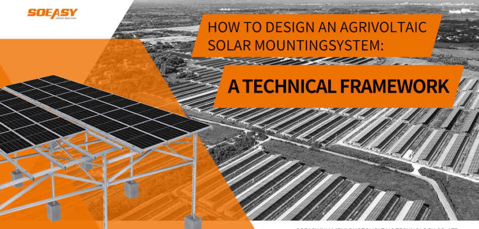
 The agrivoltaic mounting structure forms the backbone of any dual-use project. Unlike a conventional ground-mount rack, an elevated solar mounting system must perform two jobs at once: it holds the solar array securely, and it creates a productive growing environment underneath. To achieve this, you need a structured design approach. The following six engineering domains define a successful agrivoltaic support system.
1. Agricultural Compatibility Design
Crop needs drive the entire design process. Before you optimize for energy yield, you must first understand the biological and operational requirements of the plants below.
1.1 Vertical Clearance Requirements
Crop morphology and farm machinery determine the minimum height of your elevated solar mounting system.
- Vegetable and arable crops: Keep the lowest module edge at least 2.5 meters above the mature plant canopy. This prevents humid, stagnant air pockets that encourage disease.
- Orchards and vineyards: Raise the clearance to 3.5–4.0 meters or higher to accommodate tree height and the reach of harvesting equipment.
- Mechanized farming: Where tractors, harvesters, or sprayers operate, maintain a structural headroom of ≥3.5 meters, adding a safety margin above the tallest machine.
1.2 Light Distribution and Shade Management
An agrivoltaic mounting structure must never cast a solid blanket of shade. Instead, you should modulate the light carefully.
- Spacing strategies: Introduce intentional gaps between modules or module strings to achieve your target Photosynthetically Active Radiation (PAR) transmittance.
- Tilt angle decisions: Reduce the panel tilt a few degrees from the maximum-energy angle to let more diffuse light reach the crops. You can also use seasonal adjustable tilt or single-axis trackers to alter the shading pattern throughout the day.
- Bifacial modules: Capturing ground and crop-reflected light helps, but you must reassess the resulting shade-to-light ratio to keep it crop-friendly.
1.3 Column Grid and Farm Machinery Access
The layout of the agrivoltaic support system must integrate smoothly with daily farm logistics.
- Row spacing: Set the north-south pile spacing wider than the working width and turning radius of the largest farm machine.
- Column placement: Align every post with the planting beds, irrigation lines, and greenhouse ventilation openings to avoid permanent obstructions.
- Collaborative design: Bring agronomists and farm operators into the planning process early, before you pour any foundation.
2. Structural Engineering and Load Determination
Lifting panels high off the ground exposes them to stronger wind forces. Consequently, you cannot simply reuse a standard ground-mount recipe for this elevated solar mounting system.
2.1 Wind and Snow Loads
- Wind load analysis: Because of the increased height and open exposure, obtain pressure coefficients from wind tunnel tests or Computational Fluid Dynamics (CFD) simulations rather than generic building codes. Pay close attention to gust effects and vortex shedding.
- Snow management: Beyond static weight, snow sliding from tilted modules creates a second hazard. You need to integrate snow guards or retention rails into the agrivoltaic mounting structure to protect crops and greenhouse films from sudden snow slides.
2.2 Foundation Selection and Soil Preservation
Your foundation must deliver structural stability while safeguarding the arable soil.
- Preferred foundation types: Use prestressed concrete driven piles or helical steel piles.
- Installation depth: Drive the pile cap below the active cultivation layer. This minimizes topsoil disturbance and makes full land restoration possible later.
- Hydrological safety: Position all column bases and electrical connections above the historical maximum groundwater or flood level.
3. Corrosion Protection in Aggressive Agricultural Environments
Farm environments attack steel in ways a typical solar park never experiences. Fertilizer mist, pesticide spray, animal waste, and constant humidity form a corrosive chemical soup. Therefore, you must specify protective measures accordingly.
3.1 Coating and Material Specification
- Corrosivity category: Select at least ISO 12944 C4 (High Corrosivity), and upgrade to C5 for intensive livestock operations or tropical humidity.
- Hot-dip galvanizing: Specify an average zinc coating thickness of ≥85 µm.
- Fastener selection: Use stainless steel (A2 or A4 grade) for all bolts, washers, clamps, and tension wires. This prevents galvanic corrosion at the joints.
3.2 Condensate Management
Galvanized steel runoff can cause leaf burn when it drips onto crops. To solve this, your elevated solar mounting system design should incorporate dedicated drip channels or deflector profiles. Route the condensate away from the plant canopy, for example by aligning drip edges above a service path rather than a crop row.
4. Electrical Safety and Lightning Protection
People and machinery move under live DC circuits every day, so safety demands a zero-tolerance approach.
- Equipotential bonding: Connect all metallic components—the agrivoltaic support system frame, cable trays, inverter housings—into a single continuous grounding grid.
- Lightning protection: You can use the metal framework as a natural down conductor, but first verify its continuity and current-carrying capacity. This prevents dangerous side-flashing to crop structures or personnel.
- Cable management: Route all DC cables inside protective conduits or elevated trays well above the human reach envelope. Never leave an exposed connector at an accessible height.
5. Operations and Maintenance Integration
An elevated solar mounting system must enable safe, efficient service work without disrupting the agricultural calendar.
- Maintenance corridors: Build dedicated walkways or access alleys into your structural grid. These allow robotic or manual panel cleaning without trampling the crops.
- Equipment positioning: Place combiner boxes and string inverters along the perimeter or in central service alleys. That way, technicians can perform most routine tasks from the ground or a lightweight mobile platform.
6. Regulatory Compliance and Land-Use Policy
Agrivoltaic projects face strict land-use rules designed to protect food production. Your agrivoltaic support system design must clearly demonstrate compliance.
- Common mandates: Expect requirements for a minimum panel height (e.g., 2.5 m), a minimum row spacing (e.g., 8 m), and a maximum land coverage ratio.
- Documentation: Engineering drawings should clearly show the achieved clearance heights, column spacing, and calculated light transmittance figures.
- Early coordination: Align the structural design team, agronomists, and local permitting officers during the concept phase. A structure that prevents real farming does not qualify as a compliant agrivoltaic installation—it is simply a high solar rack on unproductive land.
Conclusion
An agrivoltaic mounting structure is far more than a tall rack; it is an engineered interface between energy and agriculture. To build a successful elevated solar mounting system, you need to follow a clear hierarchy: first, guarantee agricultural viability through adequate height and smart light modulation; then, secure structural and electrical integrity against harsh environmental and operational loads. When you apply this disciplined, domain-integrated approach to your agrivoltaic support system, you create a true dual-use asset—one that generates clean power and productive harvests on the very same land.
Agri-voltaic mounting manufacturing: SOEASY SOLAR