English

A solar mounting structure does far more than hold panels in place. It forms the foundation of system safety, structural stability, and power generation performance. A well-designed mounting system reduces construction costs, shortens installation timelines, and ensures more than 25 years of reliable operation. Different projects face vastly different installation environments and technical requirements, so mounting design must be adapted to each unique site. This article outlines the key factors that engineers and installers must consider when designing a solar mounting system.
Understand the Project Requirements First
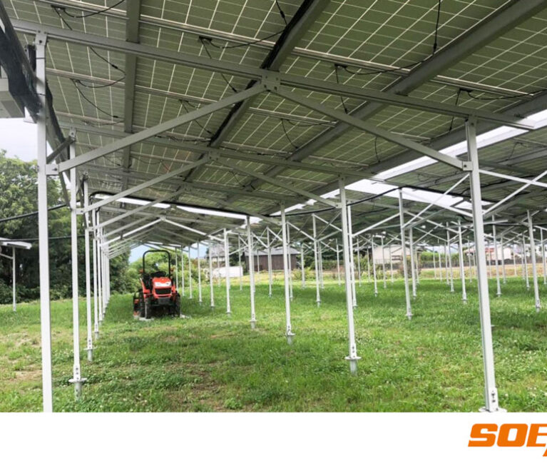
The first step in any mounting system design is understanding the project’s specific requirements. Different application scenarios demand different solutions. Ground mount systems serve large utility-scale projects, while rooftop mounting systems address commercial and industrial buildings. Solar carport systems combine energy generation with vehicle protection. Agrivoltaic systems integrate farming with solar production. Floating solar systems operate on water bodies, and balcony solar mounting systems serve urban residential applications .
Project scale also matters. Residential systems require simple, cost-effective designs. Commercial and industrial projects demand higher structural capacity and faster installation. Utility-scale solar farms need robust engineering with optimized material usage across thousands of mounting units .
Evaluate Site Conditions
Site conditions directly determine foundation selection and mounting layout.
Terrain and Topography
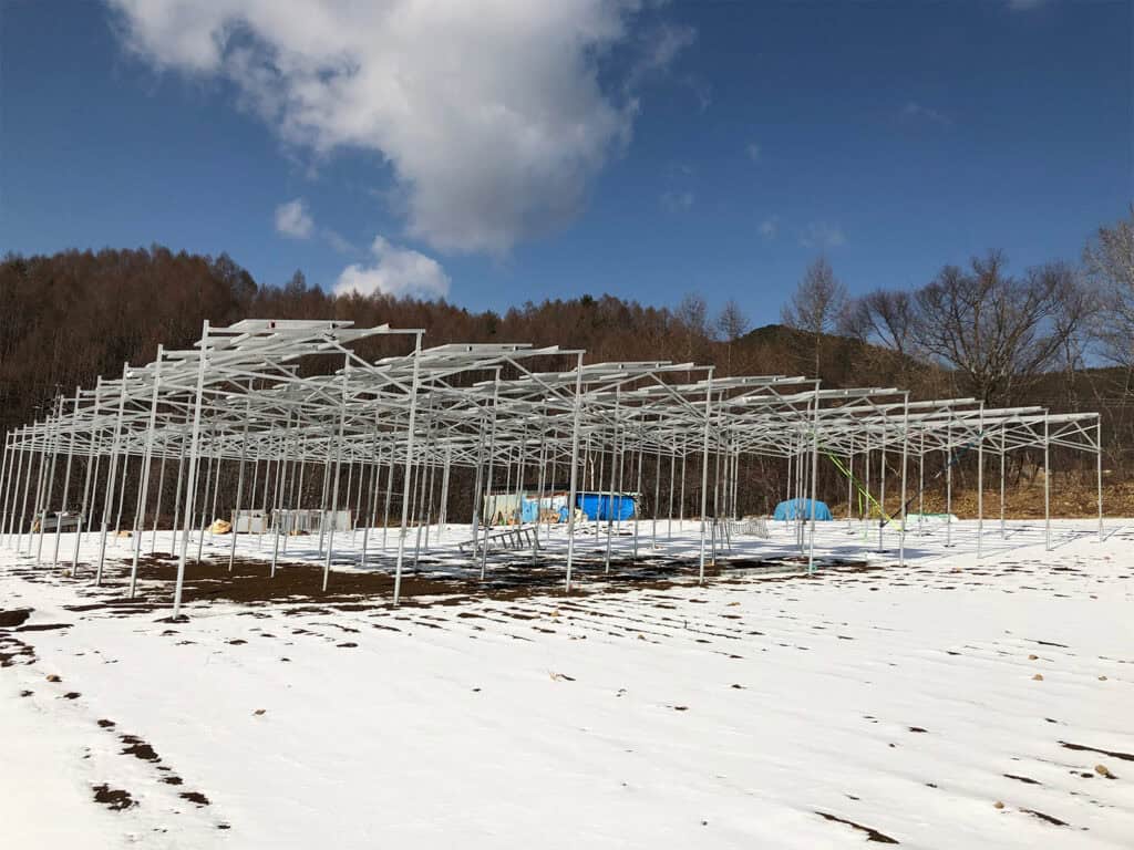
The shape of the land influences structural design significantly. Flat ground allows standard layouts, while sloped land requires terrain-adaptive solutions. Mountainous terrain and irregular topography demand customized structural approaches. SoEasy Solar’s TerraSP single-pole system uses modular design to adapt to diverse terrain, from flat areas to sloping plots .
Soil Conditions
Soil type is the primary factor in foundation selection. Key considerations include soil bearing capacity, rock content, and groundwater level. For a 7.6MW project in Bosnia and Herzegovina’s mountainous region, SoEasy engineers conducted detailed topographic analysis and implemented a segmented mounting layout that followed the terrain contours .
Roof Conditions
For rooftop projects, the roof type determines the attachment method. Flat roofs may use ballasted or penetrated systems. Metal roofs with standing seams allow clamp-on solutions that do not penetrate the waterproofing. Tile roofs require specialized roof hooks that distribute load without damaging the tiles .
Environmental Load Analysis
Wind Load
Wind is the governing load for most mounting structures. Tilted panels act like airfoils; wind passing underneath creates uplift that pulls clamps and fasteners upward . Designers must evaluate local design wind speeds, building height, terrain category, and pressure distribution across the array. In coastal regions such as the Philippines, SoEasy Solar has engineered systems that withstand typhoon-strength winds through enhanced wind-load designs .
Snow Load
Snow adds mass to the structure and can cause bending, buckling, or collapse. Designers must consider both average accumulation and extreme single-event snow loads. According to industry standards, tilts above 30 degrees allow natural snow shedding, while systems below 15 degrees must be designed for full snow load.
Seismic Considerations
Projects in seismic zones require additional structural analysis. Seismic forces act horizontally and can cause panels to slide or racks to overturn if anchorage is insufficient. Ballasted systems need special attention because inertia forces act on the mass of the ballast itself .
Corrosion Environment
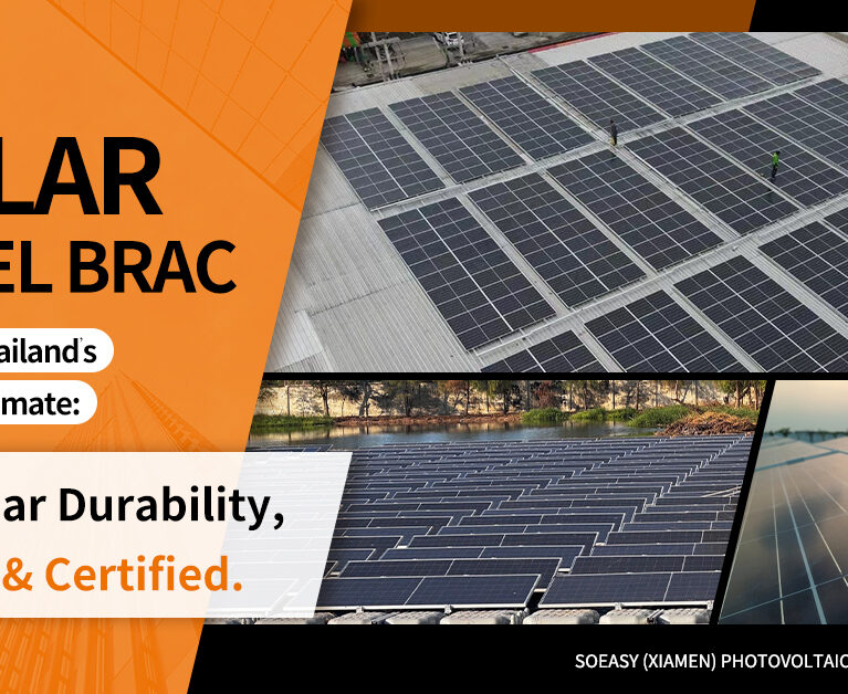
The installation environment determines material selection. Inland areas with moderate conditions allow standard galvanized steel. Coastal regions with salt spray require enhanced corrosion protection. The industry standard for corrosion classification uses C1 through C5 ratings; C5 environments demand specialized materials such as Zn-Al-Mg coated steel or stainless steel fasteners.
Choose the Right Structural Materials
Aluminum Alloy
Aluminum offers lightweight construction with excellent corrosion resistance. The natural oxide layer protects against salt and humidity without additional coatings . Aluminum is the first choice for rooftop systems and distributed PV projects where roof load capacity is limited. SoEasy’s TerraAL aluminum system features anodized aluminum construction with lightweight structure and superior corrosion resistance for coastal and challenging environments .
Hot-Dip Galvanized Steel
Galvanized steel provides high strength at a moderate cost. The thick zinc coating protects against corrosion for most standard environments. This material is the default choice for large-scale ground-mounted power plants and heavy-load applications .
Zn-Al-Mg Coated Steel
Zinc-aluminum-magnesium coated steel delivers superior corrosion resistance with self-healing properties at cut edges. This material is particularly well suited for coastal and high-humidity regions where standard galvanizing may not provide sufficient protection .
Stainless Steel Fasteners
Fastener material is often overlooked but critical for long-term reliability. In marine environments within 1-2 kilometers of the sea, A4-316L stainless steel fasteners are recommended. Standard 304 stainless can pit in salt air; carbon steel fasteners should never be mixed with aluminum rails without isolation washers .
Structural Design Considerations
Module Layout
Module orientation affects both power generation and structural loading. Landscape or portrait mounting changes the load distribution on rails and clamps. Array spacing must prevent shading between rows while maintaining structural integrity.
Tilt Angle Optimization
Tilt angle impacts energy yield, drainage, and snow shedding. For flat roofs, common angles range from 5 to 15 degrees . In agrivoltaic applications, SoEasy’s Demeter system uses a 30-degree tilt to maximize solar capture while maintaining clearance for agricultural machinery .
Structural Strength
The key structural components—rails, beams, front pillars, rear pillars, and bracing systems—must all meet strength and stiffness requirements. Under design standards such as GB 50797, column top deflection must not exceed 1/60 of column height, and flexural member deflection limits vary by application .
Connection Design
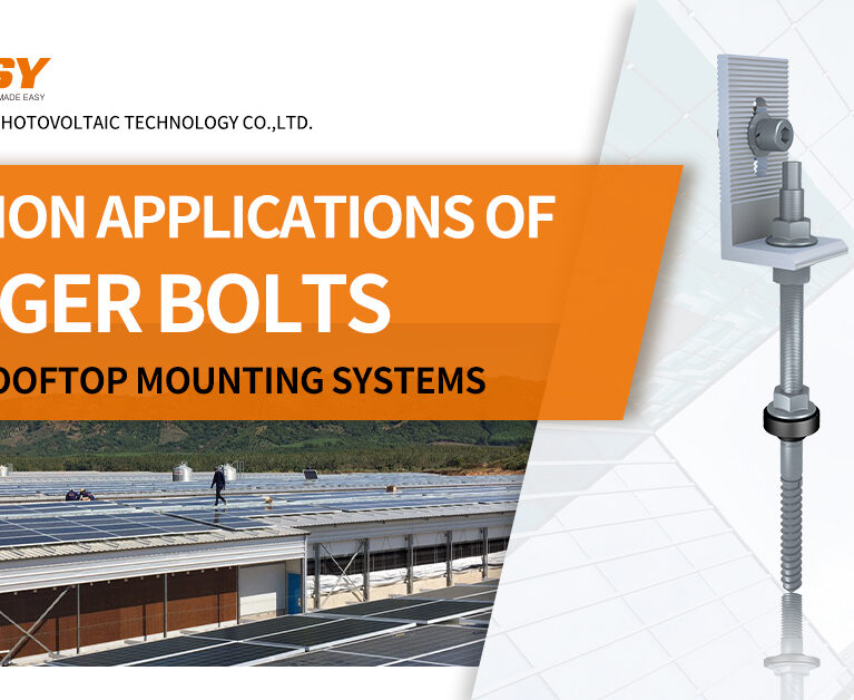
Connection reliability determines overall system safety. Mid-clamps and end-clamps must provide secure module fixation under all load conditions. Rail connectors, L-feet, roof hooks, and hanger bolts must all be specified correctly for the application .
Installation Efficiency
Modular Design
Reducing the number of component types simplifies logistics and speeds assembly. SoEasy’s TerraSP uses modular design to adapt to diverse terrain while reducing on-site complexity .
Pre-Assembled Components
Pre-assembly reduces on-site labor and minimizes error. SoEasy’s flat roof ballasted systems feature full pre-assembly that reduces installation time by more than 40% .
Standardized Connections
When connections are standardized across the system, crews require less training and make fewer errors. Universal connection designs speed installation and reduce the need for specialized tools .
Operation and Maintenance Considerations
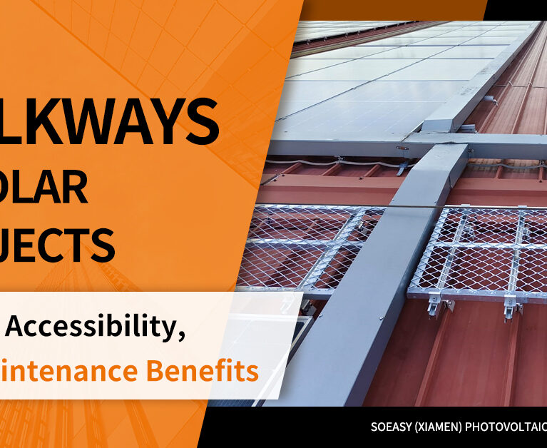
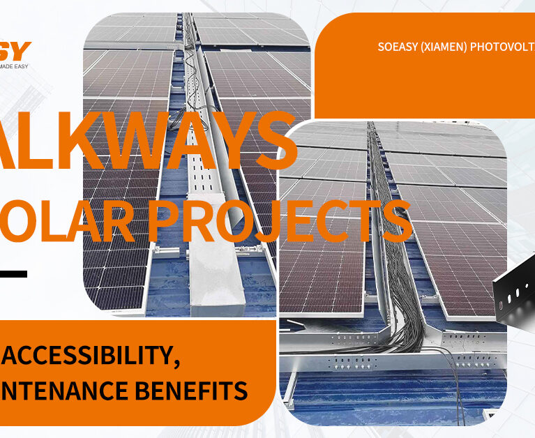
Accessibility
Walkways and access paths allow maintenance personnel to reach all areas of the array. SoEasy’s projects include anti-slip walkways and cable tray systems that protect personnel and cables while simplifying inspection and repair .
Cable Management
Cable trays and clips organize DC and AC cables, reducing the risk of abrasion and electromagnetic interference. Proper cable management also simplifies fault tracing and maintenance .
Drainage and Ventilation
Adequate drainage prevents water accumulation that can accelerate corrosion. Ventilation reduces module operating temperatures and improves energy yield. In agrivoltaic systems, these factors also affect crop health.
Long-Term Inspection
Systems designed for easy inspection allow technicians to check fasteners and connections without dismantling components. This reduces maintenance costs and extends system life.
Compliance with International Standards
Structural Design Standards
Projects must comply with local codes. North America follows ASCE 7, Europe uses Eurocode EN 1991, Australia and New Zealand use AS/NZS 1170, and Japan follows JIS standards . SoEasy Solar’s products are tested and certified according to multiple international standards, including ISO 9001, TÜV, CE, and AS/NZS 1170.2 .
Material Standards
Material selection must meet local specifications. The following table summarizes key compliance considerations for different regions and environments :
| Region | Primary Standard | Key Requirements |
|---|---|---|
| United States | ASCE 7 | Wind uplift calculations, seismic provisions |
| Europe | Eurocode EN 1991-1-4 | National annexes modify base wind/snow values |
| Australia/New Zealand | AS/NZS 1170 | Cyclone regions need special detailing |
| Japan | JIS Standards | Seismic and typhoon design requirements |
| China | GB 50797 | 25-year design life, corrosion protection minimums |
Engineering Documentation
Comprehensive documentation supports project approval and financing. Structural calculation reports, load analysis reports, and detailed installation drawings are essential for EPC contractors, owners, and certification bodies .
Balancing Performance, Cost, and Durability
Effective mounting design balances multiple competing factors. Material cost must be weighed against installation efficiency. Higher-grade materials may increase upfront cost but reduce long-term maintenance. The goal is to achieve the lowest lifecycle cost while maintaining safety margins.
How SoEasy Solar Supports Custom Mounting System Design
SoEasy Solar provides comprehensive design support based on over 17 years of industry experience and more than 70 patents . Services include customized mounting system design, structural calculation services, wind and snow load analysis, foundation recommendations, material selection support, and project-specific engineering optimization. The company’s products are engineered and tested to meet international standards, ensuring compliance and smooth project approval.
Frequently Asked Questions: Solar Mounting System Design
What is the most important factor in solar mounting design?
Wind load analysis is typically the governing factor, as wind uplift usually determines structural requirements .
Which material lasts longest in coastal environments?
Zn-Al-Mg coated steel or aluminum with appropriate anodization, paired with A4-316L stainless steel fasteners.
How long should a solar mounting system last?
Industry standard design life is 25 years .
Do all mounting systems need custom engineering?
Most projects require some level of custom design because site conditions, loads, and codes vary significantly .
Does SoEasy Solar provide custom mounting solutions?
Yes. SoEasy offers customized design, structural calculations, and material recommendations for all project types.
The Right Design Starts with Engineering Excellence
Solar mounting system design is a comprehensive engineering process that requires careful evaluation of project requirements, site conditions, environmental loads, material properties, installation efficiency, and maintenance needs. Only through scientific structural design and appropriate material selection can a PV system achieve long-term safety, lower lifecycle costs, and maximum power generation.
SoEasy Solar provides customized, high-reliability photovoltaic mounting solutions for customers worldwide. Visit our solutions page to explore our product range, or contact our engineering team for project-specific design support.